Sep 18, 2026CNC Machining Guides
Custom Machined Shafts: Key Drawing and Design Requirements
Learn how to specify shaft materials, diameters, shoulders, threads, keyways, runout, surface finish, heat treatment, inspection, and RFQ requirements.
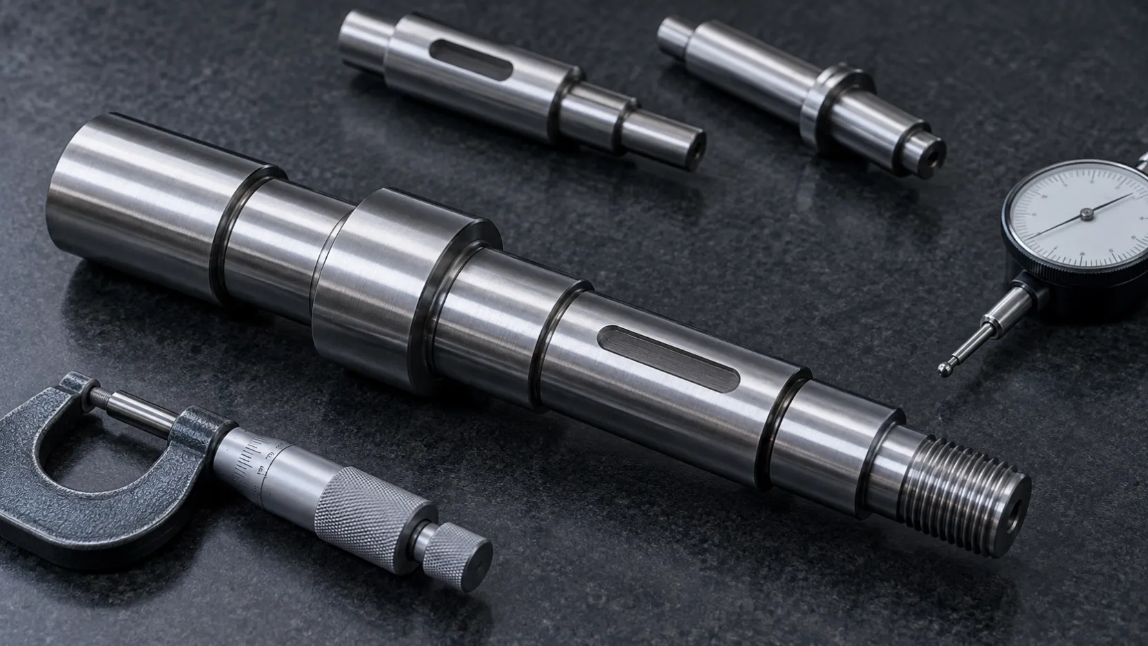
Custom machined shafts are used to transmit motion, support rotating components, locate assemblies, or provide precision interfaces for bearings, bushings, seals, couplings, and fasteners.
A shaft drawing must define more than its overall length and largest diameter. Its performance may depend on the relationship between multiple diameters, shoulders, threads, grooves, keyways, surface finishes, heat treatment, and mating components.
This guide explains the key information required when designing or requesting a quotation for a custom CNC machined shaft.
What Is a Custom Machined Shaft?
A custom machined shaft is manufactured to a customer drawing rather than selected from a standard catalogue.
Custom features may include:
- Multiple stepped diameters
- Shoulders
- Bearing seats
- Bushing interfaces
- External or internal threads
- Grooves
- Keyways
- Flats
- Cross holes
- Tapers
- Retaining-ring grooves
- Internal bores
- Special end forms
- Heat treatment
- Grinding
- Coating
- Customer-specific inspection requirements
The manufacturing process should be reviewed according to the complete geometry, material, quantity, tolerances, surface finish, and application.
Define the Shaft’s Function
Before assigning dimensions and tolerances, define what the shaft must do.
Consider whether the shaft:
- Rotates continuously or intermittently
- Slides axially
- Supports a radial load
- Transmits torque
- Carries a bearing
- Fits inside a bushing
- Contacts a seal
- Locates a coupling
- Requires electrical conductivity
- Operates in a corrosive environment
- Experiences impact or fatigue
- Must remain lightweight
- Requires a cosmetic finish
Functional information helps determine which features are critical.
Common Custom Shaft Types
Stepped Shafts
A stepped shaft contains two or more controlled diameters.
Steps may provide:
- Bearing locations
- Bushing interfaces
- Component location
- Assembly clearance
- Retaining shoulders
- Thread transitions
The drawing should define diameter limits, step locations, shoulder relationships, corner reliefs, and the required geometric relationship between features.
Threaded Shafts
Threaded shafts may contain threads on one or both ends or along an intermediate section.
Specify:
- Thread standard
- Nominal size
- Pitch
- Tolerance class
- Thread length
- Thread relief
- Entry chamfer
- Inspection method
- Coating condition
Clarify whether thread dimensions apply before or after coating.
Hollow Shafts
A hollow shaft includes an axial bore to reduce weight, provide a passage, or interface with another component.
Important requirements may include:
- Bore diameter
- Bore depth
- Through or blind condition
- Wall thickness
- Concentric relationship
- Internal surface finish
- Cleaning requirement
- Inspection accessibility
Long, deep, or small-diameter bores require additional manufacturing review.
Shafts with Keyways or Flats
Keyways and flats may transmit torque, locate a component, or provide wrench access.
The drawing should define:
- Width
- Depth
- Length
- End condition
- Position relative to datums
- Corner radius
- Surface finish
- Burr requirements
- Relationship to other shaft features
A turned shaft with keyways, flats, or cross holes may require both turning and milling operations.
Select the Material According to Service Conditions
Possible shaft materials may include:
- Carbon steel
- Alloy steel
- Stainless steel
- Aluminum alloy
- Brass or copper alloy
- Engineering plastic
- Other customer-specified materials
Material selection should consider:
- Strength
- Stiffness
- Fatigue
- Impact
- Wear
- Corrosion
- Temperature
- Weight
- Machinability
- Heat treatment
- Surface finishing
- Cost
- Certification
Do not specify only “steel” or “stainless steel.” Provide the exact grade and condition.
Define Every Functional Diameter
A shaft may include different diameters for bearings, bushings, seals, couplings, threads, and clearance.
For each functional diameter, define:
- Nominal size
- Upper and lower limits
- Fit requirement
- Surface finish
- Length
- Edge condition
- Coating condition
- Inspection requirement
Avoid applying the tightest tolerance to every diameter.
A bearing seat may require tighter control than a non-functional clearance diameter. The drawing should make that distinction clear.
Specify Shaft-to-Bushing or Shaft-to-Bearing Fits
A nominal diameter alone does not fully define the mating relationship.
Provide information about:
- Mating bore
- Required clearance or interference
- Operating temperature
- Lubrication
- Speed
- Load
- Assembly method
- Coating thickness
- Wear allowance
- Removal requirements
The shaft and mating bore should be evaluated as a system.
Learn more about mating bushings in Custom CNC Bushings: Materials, Fits, and Design Considerations.
Control Diameter Relationships
Shaft performance may depend on the relationship between different cylindrical features.
Critical controls may include:
- Coaxiality of bearing seats
- Runout of seal surfaces
- Runout of shoulders
- Relationship between threads and shaft axis
- Relationship between outside diameters and an internal bore
- Position of milled features relative to the rotational axis
Use a functional datum system and suitable geometric tolerances.
Do not add very tight runout requirements without confirming the functional need and inspection method.
Define Shoulder Locations and Faces
Shoulders may locate bearings, bushings, spacers, couplings, or other assembly components.
Define:
- Shoulder diameter
- Axial location
- Face perpendicularity
- Face runout
- Surface finish
- Corner radius
- Relief groove
- Mating component clearance
A large corner radius may interfere with a mating component. A sharp internal corner may be impractical or create stress concentration.
Include an appropriate radius, chamfer, or relief that supports both function and manufacturing.
Account for Fillets and Relief Grooves
Transitions between shaft diameters require careful design.
Possible features include:
- Fillet radius
- Undercut
- Thread relief
- Grinding relief
- Tool-clearance groove
These features may help provide tool access or prevent interference with mating components.
The drawing should define the geometry rather than leaving the transition ambiguous.
Review the feature with the component that seats against the shoulder.
Consider Long and Slender Shaft Geometry
Long, slender shafts may deflect or vibrate during machining.
Important factors include:
- Overall length
- Smallest diameter
- Unsupported length
- Material
- Heat treatment
- Required straightness
- Diameter tolerance
- Surface finish
- Center-hole availability
- Part handling
- Final inspection method
A shaft may meet local diameter requirements but fail assembly because of excessive straightness error or distortion.
Long shafts may require special workholding, support, process sequencing, or finishing operations.
Specify Straightness Requirements Where Necessary
Straightness may be important for:
- High-speed rotation
- Long bearing spans
- Sliding assemblies
- Seal contact
- Alignment
- Multi-bearing systems
The drawing should define:
- Which feature requires straightness control
- Datum or free-state condition where relevant
- Measurement length
- Final material and heat-treatment condition
- Inspection method
Avoid using an undefined note such as “shaft must be straight.”
Define Keyways Completely
For a keyway, specify:
- Width
- Depth
- Length
- Position
- End shape
- Corner radius
- Relationship to shaft axis
- Relationship to another feature
- Surface finish
- Burr requirements
If the keyway transmits torque, review the shaft material, key material, load, and stress concentration.
For multiple keyways or flats, define their angular relationship.
Define Cross Holes and Radial Features
Cross holes may be used for:
- Pins
- Lubrication
- Fasteners
- Safety wire
- Assembly
- Fluid passage
Specify:
- Diameter
- Position
- Angular orientation
- Through or blind condition
- Countersink or chamfer
- Burr requirement
- Intersection with internal bores
- Cleaning requirement
Intersecting holes can create internal burrs that are difficult to access. Define the required condition clearly.
Specify Thread Requirements
A complete thread callout should include:
- Thread system
- Nominal diameter
- Pitch
- Tolerance class
- Thread length
- Minimum full thread
- Relief
- Entry chamfer
- Left- or right-hand direction
- Coating condition
- Inspection requirement
If torque, preload, or fatigue is critical, the responsible engineer should review the complete joint design rather than selecting the thread only from available shaft diameter.
Define Surface Finish on Functional Areas
Different areas of one shaft may require different surface finishes.
Functional surfaces may include:
- Bearing seats
- Seal surfaces
- Bushing interfaces
- Sliding diameters
- Coupling fits
- Thrust shoulders
- Thread flanks
Surface roughness should be defined only where needed.
A dimensional tolerance does not automatically establish an appropriate surface finish.
Consider Heat Treatment
Heat treatment may be used to change hardness, strength, wear behavior, or dimensional stability.
Specify:
- Exact material
- Heat-treatment process
- Target hardness
- Case-depth requirement where relevant
- Protected areas
- Final machining or grinding
- Distortion limits
- Inspection condition
- Required certification
Heat treatment can change shaft dimensions and straightness.
Critical shaft features may require finishing after heat treatment.
Consider Coating and Surface Treatment
Possible requirements may include:
- Plating
- Passivation
- Black oxide
- PVD coating
- Other customer-specified treatments
Define:
- Coating type
- Thickness
- Masked surfaces
- Thread protection
- Bearing and seal surfaces
- Dimensions before coating
- Dimensions after coating
- Final inspection condition
- Required certificate
Coating thickness can change fits and thread condition.
Plan the Manufacturing Sequence
A custom shaft may require:
- CNC turning
- Milling
- Drilling
- Threading
- Heat treatment
- Grinding
- Coating
- Final inspection
The order of operations affects datum control, distortion, surface finish, and cost.
Send the complete drawing instead of separating each feature into unrelated enquiries.
Define Inspection Requirements
Critical shaft characteristics may include:
- Diameter
- Length
- Shoulder position
- Straightness
- Runout
- Surface roughness
- Thread condition
- Keyway width and position
- Cross-hole position
- Hardness
- Coating thickness
Possible inspection equipment may include micrometers, gauges, indicators, surface-finish instruments, or other appropriate measurement systems.
Identify required reports and sampling before quotation.
Common Shaft Drawing Problems
Quotation or production may be delayed by:
- Missing material grade
- Undefined mating fits
- Tight tolerances applied to every diameter
- Missing runout datum
- Incomplete thread callout
- Undefined shoulder relief
- Keyway dimensions missing
- No straightness requirement for a long shaft
- Surface finish not specified
- Heat treatment added after quotation
- No coating allowance
- Drawing and 3D model revisions do not match
- Unclear inspection requirements
A drawing review before RFQ submission helps reduce assumptions.
Custom Shaft RFQ Checklist
Provide:
- Current 2D drawing
- Matching 3D model
- Exact material and condition
- Prototype and production quantities
- Functional diameters and fits
- Mating-component information
- Shoulder locations
- Runout and straightness requirements
- Keyways, flats, and cross holes
- Complete thread callouts
- Surface roughness
- Heat treatment
- Coating
- Inspection and documentation
- Target delivery date
If the application is confidential, provide at least the functional information required to review manufacturing feasibility.
Request a Custom Shaft Review
Zync Precision manufactures custom CNC machined shafts according to customer drawings for prototype, small-batch, and repeat-production enquiries.
Send the drawing and 3D model together with the material, quantity, fits, tolerances, heat treatment, finishing, and inspection requirements.