Sep 18, 2026CNC Machining Guides
Custom CNC Bushings: Materials, Fits, and Design Considerations
Learn how to specify materials, bore and shaft fits, tolerances, flange geometry, lubrication, surface finish, inspection, and RFQ details for custom CNC bushings.
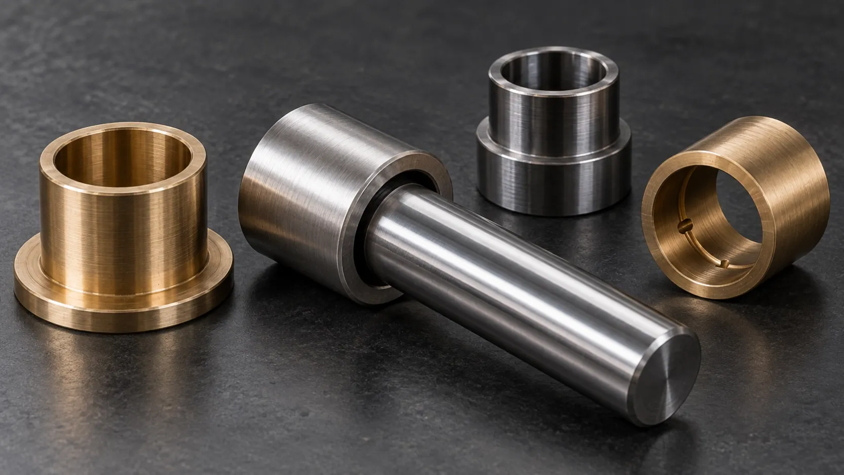
Custom bushings may appear simple, but their performance depends on the relationship between the bore, outside diameter, length, flange, mating shaft, housing, material, lubrication, surface finish, and operating conditions.
A bushing drawing should define more than nominal dimensions. It should communicate how the component is installed, how the shaft moves, which surfaces are critical, and how the finished part will be inspected.
This guide explains the main considerations when requesting a quotation for custom CNC machined bushings.
What Is a Custom Machined Bushing?
A machined bushing is a cylindrical component used to support, locate, guide, separate, or protect a mating shaft or assembly feature.
Unlike a standard catalogue bushing, a custom bushing is manufactured to a customer drawing and may include:
- Non-standard bore and outside diameter
- Special length
- Flange
- Shoulder
- Multiple outside diameters
- Internal or external threads
- Cross holes
- Lubrication grooves
- Slots
- Reliefs
- Special materials
- Heat treatment
- Surface finishing
- Customer-specific inspection requirements
The manufacturing method and material should be reviewed according to the complete drawing and application.
Common Custom Bushing Types
Straight Sleeve Bushings
A straight sleeve bushing has a generally cylindrical outside diameter and bore.
It may be used for:
- Shaft guidance
- Spacing
- Wear protection
- Alignment
- Replaceable interfaces
- General mechanical assemblies
Important drawing requirements include the bore, outside diameter, length, edge condition, fit, surface finish, and material.
Flanged Bushings
A flanged bushing includes a larger-diameter flange at one end.
The flange may provide:
- Axial location
- A thrust surface
- Installation control
- A mounting face
- Retention within an assembly
The drawing should define flange diameter, flange thickness, face runout where relevant, and the relationship between the flange face and the bore.
Stepped or Shoulder Bushings
A stepped bushing contains more than one outside diameter or internal diameter.
It may be used where the component must locate against a housing shoulder or interface with different assembly features.
Important requirements may include:
- Step locations
- Shoulder width
- Concentricity between diameters
- Perpendicularity of shoulder faces
- Relief at internal corners
- Assembly direction
Threaded Bushings
Threaded bushings may include internal threads, external threads, or both.
Specify:
- Thread standard
- Nominal size
- Pitch
- Thread class
- Thread length
- Entry chamfer
- Runout or relief
- Coating condition
- Inspection method
Clarify whether thread dimensions apply before or after surface treatment.
Lubrication-Groove Bushings
Some bushings require internal grooves, holes, or channels for lubricant distribution.
The drawing should define:
- Groove profile
- Width and depth
- Start and end position
- Connection to lubrication holes
- Edge condition
- Surface-finish requirement
- Cleaning requirement
Lubrication features should be reviewed with the operating motion, load, lubricant, and installation orientation.
Start with the Mating Shaft and Housing
A bushing cannot be designed correctly without considering the mating components.
Provide information about:
- Shaft diameter and tolerance
- Shaft material
- Shaft hardness
- Shaft surface finish
- Housing bore and tolerance
- Installation method
- Required clearance or interference
- Operating temperature
- Lubrication
- Rotational or sliding motion
- Load direction
- Expected wear
- Service environment
The bushing, shaft, and housing form a system. Changing one component may change the required fit and performance of the others.
Define the Bore Fit
The bore-to-shaft relationship may require a clearance, transition, or other controlled fit depending on the function.
Important considerations include:
- Required running clearance
- Lubricant film
- Shaft speed
- Sliding frequency
- Temperature change
- Material expansion
- Shaft alignment
- Contamination
- Surface roughness
- Wear allowance
Do not specify only the nominal bore and shaft diameter. Define the acceptable limits or the required fit system.
A clearance that is too small may increase friction or cause seizure under temperature change. Excessive clearance may reduce alignment or increase movement and wear.
The responsible designer should approve the final fit according to the application.
Define the Outside-Diameter Fit
The bushing outside diameter may be designed for:
- Clearance installation
- Slip fit
- Transition fit
- Press fit
- Retention using adhesive
- Threaded installation
- Mechanical retention
For press-fit bushings, consider:
- Housing material
- Housing wall thickness
- Bushing wall thickness
- Interference
- Installation method
- Edge chamfers
- Distortion
- Bore-size change after installation
- Operating temperature
- Removal or replacement requirements
A press fit can reduce or change the final bore size. If the installed bore is critical, this must be considered during design and inspection planning.
Select the Material According to Function
Possible bushing materials may include:
- Stainless steel
- Carbon or alloy steel
- Brass
- Bronze-related alloys
- Aluminum alloys
- Engineering plastics
- Other customer-specified materials
The material should be selected according to:
- Load
- Wear
- Corrosion
- Shaft material
- Friction
- Lubrication
- Temperature
- Weight
- Electrical requirements
- Machinability
- Heat treatment
- Cost
- Certification
Do not select a material based only on appearance or familiarity.
Steel Bushings
Steel may be considered when strength, stiffness, wear performance, or heat-treatment capability is required.
Review:
- Exact grade
- Hardness
- Heat treatment
- Corrosion protection
- Shaft compatibility
- Final grinding or finishing
- Dimensional condition after treatment
Stainless-Steel Bushings
Stainless steel may be considered for corrosion resistance and durability.
Review:
- Stainless grade
- Operating environment
- Galling risk
- Shaft material
- Lubrication
- Passivation
- Surface finish
- Magnetic requirements
Brass or Bronze-Type Bushings
Copper-based alloys may be considered for bearing, wear, corrosion, or low-friction applications, depending on the exact alloy.
Review:
- Exact alloy
- Load
- Speed
- Lubrication
- Shaft hardness
- Operating temperature
- Regulatory requirements
- Material certification
Do not treat all brass or bronze materials as interchangeable.
Engineering-Plastic Bushings
Engineering plastics may be considered when low weight, corrosion resistance, electrical insulation, or particular friction behavior is required.
Review:
- Exact polymer grade
- Moisture absorption
- Temperature
- Creep
- Load
- Thermal expansion
- Chemical exposure
- Dimensional stability
- Machining deformation
“Plastic” alone is not a sufficient material specification.
Consider Wall Thickness
Thin bushing walls may deform during:
- Machining
- Clamping
- Heat treatment
- Press-fit installation
- Inspection
- Shipping
- Assembly
Very thin walls can make it difficult to maintain roundness, concentricity, and bore size.
When the wall must be thin, identify:
- Free-state dimensions
- Installed-state requirements
- Measurement method
- Acceptable roundness
- Housing support
- Installation method
The manufacturer should review the complete geometry rather than only the nominal wall thickness.
Specify Bore Surface Finish
The bore surface may be a functional sliding, rotating, locating, or sealing interface.
Define the required:
- Surface roughness
- Machining direction where relevant
- Honing or grinding requirement
- Coating
- Lubrication condition
- Cosmetic acceptance
- Inspection method
A tight bore tolerance does not automatically define an appropriate surface finish.
The shaft surface should also be considered because the two surfaces work together.
Control Concentricity and Runout Where Necessary
A bushing may contain several cylindrical features that need a controlled relationship.
Examples include:
- Bore to outside diameter
- Bore to external thread
- Bore to flange diameter
- Bore to shoulder diameter
- Flange face to bore axis
- Multiple stepped diameters
Use a functional datum system and appropriate geometric controls where these relationships affect performance.
Avoid adding tight concentricity or runout requirements without a functional reason and an agreed inspection method.
Define Flange Requirements
For a flanged bushing, identify:
- Flange outside diameter
- Flange thickness
- Face flatness
- Face perpendicularity
- Face runout
- Edge chamfer
- Surface finish
- Contact area
- Load direction
If the flange is a thrust surface, provide information about the mating face, motion, load, and lubrication.
Account for Chamfers and Edge Breaks
Chamfers can assist assembly and reduce edge damage.
Define chamfers at:
- Bore entry
- Outside-diameter entry
- Thread starts
- Press-fit entry
- Flange edges
- Lubrication holes
Avoid leaving all edge treatment to a general note when a specific edge affects installation or function.
If a sharp edge is functionally required, identify it clearly and explain the acceptance requirement.
Consider Heat Treatment and Coating
Heat treatment or surface treatment may be used to change hardness, wear behavior, corrosion resistance, or appearance.
Possible requirements may include:
- Hardening
- Stress relieving
- Plating
- Passivation
- Black oxide
- PVD coating
- Other customer-specified treatments
Define:
- Base material
- Treatment specification
- Required hardness
- Coating thickness
- Masked areas
- Dimensions before treatment
- Dimensions after treatment
- Final inspection condition
- Required certificates
Heat treatment and coating can affect bore size, fit, and distortion.
Plan Lubrication Features Carefully
If the bushing requires lubrication, provide:
- Lubricant type
- Lubrication method
- Supply-hole location
- Groove geometry
- Motion direction
- Operating orientation
- Maintenance interval
- Cleaning requirements
Grooves reduce the available bearing surface, so their size and location should be based on the application.
Do not add grooves only because they appear on another bushing design.
Define Inspection Requirements
Important bushing characteristics may include:
- Bore diameter
- Outside diameter
- Length
- Flange thickness
- Roundness
- Cylindricity
- Runout
- Concentric relationship
- Surface roughness
- Thread size
- Groove geometry
- Hardness
- Coating thickness
The drawing should define how critical features relate to the datum system.
If inspection must be performed after heat treatment, coating, or installation, state this clearly.
Common Bushing Drawing Problems
Quotation or production may be delayed by:
- No mating-shaft information
- No housing-bore information
- Undefined fit
- Missing material grade
- Missing bore surface finish
- Incomplete thread callout
- Unclear lubrication groove
- No datum structure
- Conflicting tolerances
- No coating allowance
- Undefined post-installation bore requirement
- Tight wall thickness without measurement instructions
- Different revisions of drawing and model
Reviewing these details before RFQ submission reduces assumptions.
Custom Bushing RFQ Checklist
Provide:
- Current 2D drawing
- Matching 3D model
- Bushing type
- Exact material
- Required quantity
- Shaft diameter and tolerance
- Housing bore and tolerance
- Required fit
- Bore and outside-diameter tolerances
- Surface roughness
- Lubrication requirements
- Heat treatment
- Surface finishing
- Critical geometric relationships
- Inspection documentation
- Target delivery date
If some application information is confidential, provide at least the functional conditions needed for manufacturing review.
Request a Custom Bushing Review
Zync Precision manufactures custom CNC machined bushings to customer drawings for prototype, small-batch, and repeat-production enquiries.
Send the drawing and 3D model together with the material, quantity, shaft and housing information, fits, tolerances, finishing, and inspection requirements.