Sep 18, 2026CNC Machining Guides
CNC Machining Tolerances: What Should Be Specified on a Drawing?
Learn how to specify dimensional tolerances, fits, datums, geometric controls, surface finish, and inspection requirements on CNC machining drawings.
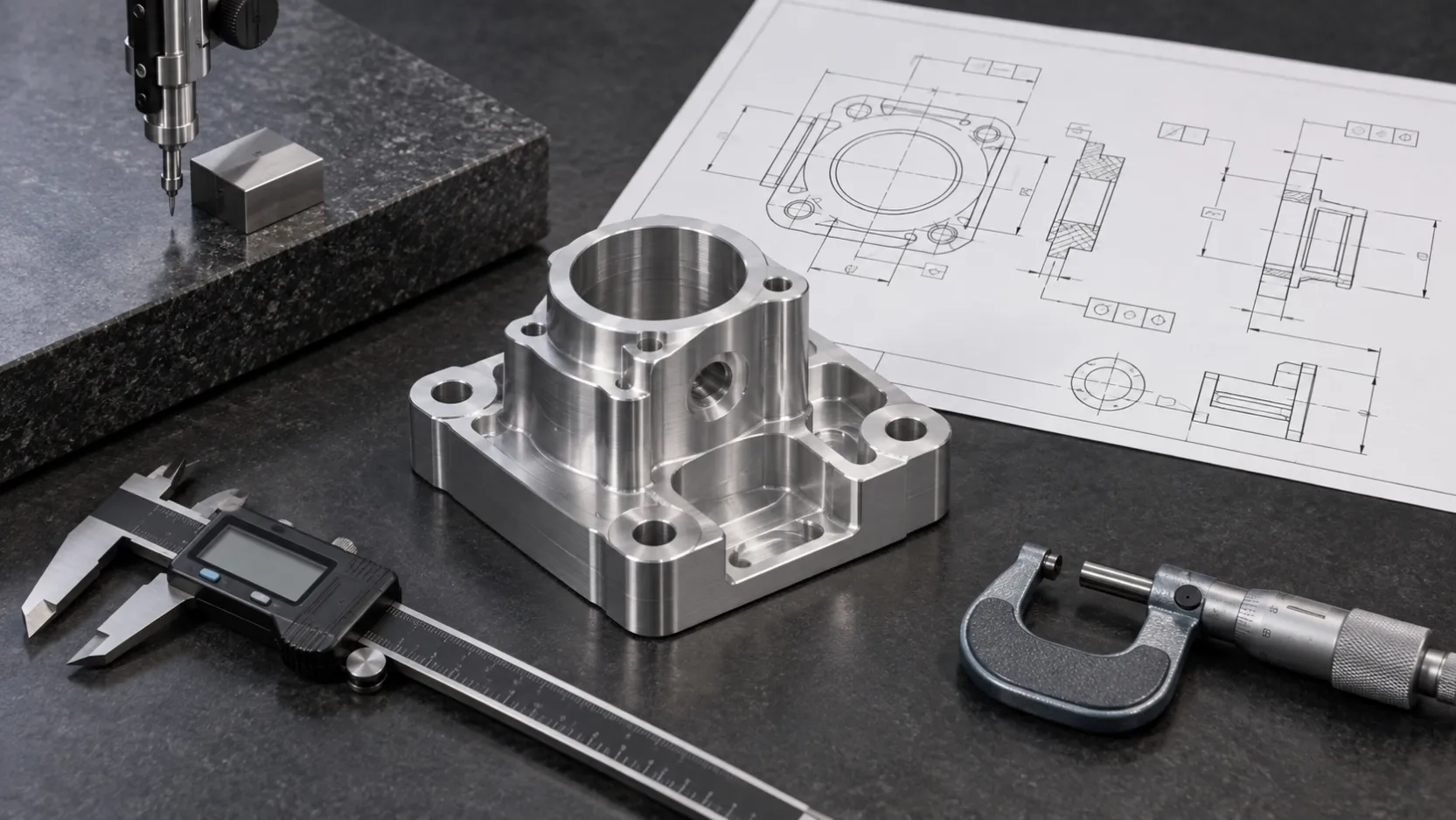
Tolerances define how much a manufactured dimension or geometric feature may vary from its nominal value. They are essential for assembly, function, interchangeability, inspection, and production control.
However, applying very tight tolerances to every feature does not automatically make a drawing better. It can increase machining time, inspection effort, production risk, and cost without improving part performance.
A useful CNC machining drawing identifies the dimensions that truly affect function and gives the manufacturer enough information to produce and inspect the part consistently.
What Is a Machining Tolerance?
A machining tolerance defines the acceptable variation from a specified dimension or geometric condition.
For example, a drawing may define a nominal diameter together with an upper and lower permitted limit. A conforming part must remain within those limits.
Tolerances can control:
- Linear dimensions
- Diameters and radii
- Angles
- Hole locations
- Flatness and straightness
- Parallelism and perpendicularity
- Position
- Concentric or rotational relationships
- Surface roughness
- Fits between mating components
The correct tolerance depends on the function of the feature, material, geometry, manufacturing process, inspection method, and assembly requirements.
Avoid Applying Tight Tolerances Everywhere
One of the most common drawing problems is assigning the same tight tolerance to every dimension.
This may create unnecessary requirements for:
- Additional machining operations
- More controlled setups
- Slower cutting parameters
- Specialized tooling
- Temperature-controlled measurement
- Additional inspection
- Increased scrap risk
- Longer production time
Separate functional dimensions from non-critical dimensions.
A mounting interface, bearing diameter, sealing surface, or precision hole position may require careful control. An external clearance surface or non-functional edge may not require the same tolerance.
The drawing should communicate design intent rather than simply demand the smallest possible variation.
Use a Clear General Tolerance
A general tolerance can cover dimensions that do not have an individual tolerance.
The drawing title block or notes should clearly define which general tolerance applies and which dimensions are excluded. Features with special functional requirements should receive their own specific tolerance.
Make sure the drawing does not contain conflicts between:
- General tolerances
- Individual dimensional tolerances
- Geometric tolerances
- Customer standards
- Referenced specifications
If more than one standard is referenced, define which requirement takes priority.
Identify Critical-to-Function Dimensions
Critical dimensions directly affect assembly, motion, sealing, alignment, load, wear, or product performance.
Examples may include:
- Bearing seats
- Mating diameters
- Press-fit or slip-fit features
- Sealing surfaces
- Hole patterns
- Shaft shoulders
- Datum mounting surfaces
- Thread engagement
- Component alignment features
- Wall thickness near a functional area
Consider marking these dimensions clearly or listing them in the inspection requirements.
A manufacturer cannot reliably determine every critical feature from geometry alone. Explain the functional relationship when it is not obvious from the drawing.
Specify Fits Between Mating Parts
A nominal diameter is not enough when two parts must fit together in a controlled way.
The drawing should communicate whether the intended relationship is:
- Clearance fit
- Transition fit
- Interference fit
- Sliding fit
- Locational fit
- Press fit
Provide the mating-component information or the required limits when necessary.
For shafts, bushings, pins, and bores, consider:
- Minimum and maximum clearance
- Assembly method
- Operating temperature
- Surface treatment
- Lubrication
- Wear
- Whether dimensions apply before or after coating
Establish a Functional Datum System
Datums create a common reference system for manufacturing and inspection.
A functional datum structure should reflect how the part is located or assembled. It may use:
- A primary mounting surface
- A secondary locating edge
- A tertiary hole or feature
- A cylindrical axis
- A defined pattern of features
A weak or unclear datum structure can make the drawing difficult to interpret. Different inspectors may establish the part differently and obtain inconsistent results.
Avoid selecting datums only because they are easy to dimension in CAD. Choose references that represent the functional location of the part whenever possible.
Use Geometric Tolerancing for Feature Relationships
Geometric tolerancing can communicate relationships that ordinary coordinate dimensions may not describe effectively.
Depending on the design, geometric controls may address:
- Flatness
- Straightness
- Parallelism
- Perpendicularity
- Position
- Profile
- Circularity
- Cylindricity
- Runout
Use geometric controls only when they express a functional requirement. The feature-control frame, datum references, material condition, and tolerance zone must be internally consistent.
Avoid stacking several controls on the same feature without understanding how they interact.
If the product requires a particular GD&T standard or drawing convention, identify it clearly.
Consider Tolerance Stack-Up
Individual dimensions may each be acceptable while the final assembly still fails because their combined variation exceeds the available clearance.
Tolerance stack-up should be reviewed across:
- Mating components
- Hole patterns
- Shoulder locations
- Assembly lengths
- Bearing positions
- Sealing interfaces
- Connected datum structures
Do not assign tolerances to one part without considering the mating components.
When several dimensions control the same functional result, a datum-based or geometric approach may communicate the requirement more clearly than a long chain of coordinate dimensions.
Define Hole and Thread Requirements Completely
Hole and thread callouts frequently cause quotation delays when information is missing.
For holes, identify as applicable:
- Diameter
- Depth
- Through or blind condition
- Counterbore or countersink
- Position tolerance
- Quantity
- Surface-finish requirement
- Relationship to datums
For threads, identify:
- Thread standard
- Nominal size
- Pitch
- Internal or external thread
- Tolerance class
- Thread depth
- Minimum full-thread requirement
- Special gauging requirement
- Coating condition
Clarify whether thread dimensions apply before or after plating, anodizing, or another surface treatment.
Specify Surface Roughness Only Where Needed
Dimensional tolerance and surface roughness are related but different requirements.
A dimension can be within tolerance while its surface is unsuitable for sealing, bearing contact, sliding, or appearance.
Identify surfaces that require controlled roughness, such as:
- Bearing seats
- Seal contact areas
- Sliding surfaces
- Precision bores
- Locating faces
- Cosmetic surfaces
Do not apply a fine surface finish to every machined surface unless it is functionally necessary.
If appearance is the main concern, describe the cosmetic acceptance requirement separately from roughness.
Account for Heat Treatment and Surface Finishing
Heat treatment and surface finishing may affect dimensions, distortion, surface condition, and inspection sequence.
The drawing or RFQ should state:
- Required heat treatment
- Required hardness
- Surface-treatment type
- Coating thickness where relevant
- Masked areas
- Dimensions controlled before treatment
- Dimensions controlled after treatment
- Post-treatment machining requirements
- Final inspection condition
A critical fit may require dimensional allowance before coating. A heat-treated part may require a finishing operation after treatment.
These requirements should be reviewed before quotation.
Make Sure the Tolerance Can Be Inspected
A tolerance is useful only when the feature can be measured with an appropriate and agreed method.
Consider:
- Feature accessibility
- Measurement reference
- Part stability
- Surface condition
- Required measurement resolution
- Sampling quantity
- Fixture requirements
- Whether a functional gauge is needed
- Whether inspection must occur before or after finishing
If a specific instrument, fixture, measurement program, or report format is required, include it in the RFQ.
Some internal features may be difficult to inspect using ordinary contact instruments. Discuss the inspection method before finalizing the requirement.
Define the Required Inspection Documentation
Different projects require different levels of documentation.
Possible requirements include:
- First-article inspection
- Dimensional report
- Critical-dimension report
- Material certificate
- Heat-treatment certificate
- Coating certificate
- Certificate of conformity
- Sampling plan
- Lot traceability
- Customer-specific inspection form
Identify the required documents before quotation. Additional reporting can require planning, measurement time, and record control.
Common Tolerance Drawing Problems
Manufacturing review may be delayed by:
- Missing general tolerances
- Conflicting tolerances
- Unclear datum references
- Excessively tight tolerances on non-critical features
- Incomplete hole or thread callouts
- Dimensions that cannot be inspected
- Different revisions of the drawing and 3D model
- Missing coating allowances
- Undefined surface roughness
- Closed tolerance chains
- Critical dimensions that are not identified
- Requirements added only after quotation
A design review before RFQ submission can prevent many of these issues.
Drawing Checklist Before Requesting a Quote
Before sending a CNC machining drawing, check that it includes:
- Current revision
- Correct units
- Material and condition
- General tolerance
- Critical dimensional tolerances
- Functional datum structure
- Required geometric controls
- Complete hole and thread callouts
- Surface roughness where necessary
- Heat treatment and finishing
- Inspection requirements
- Required documentation
- Matching 2D drawing and 3D model
If a tolerance is still under review, identify it as pending instead of allowing the manufacturer to make an assumption.
Request a Drawing and Manufacturing Review
Zync Precision reviews custom CNC machining projects according to customer drawings, materials, quantities, tolerances, finishing, and inspection requirements.
Send the current 2D drawing and 3D model together with the required quantity and project information. Critical tolerances and documentation requirements should be identified before quotation.