CNC Machining Guides
Tolerance Stack-Up for CNC Machined Assemblies: How to Prevent Fit and Alignment Failures
A buyer-focused guide to tolerance stack-up in CNC machined assemblies: functional datums, GD&T, fits, coatings, temperature, inspection and RFQ checks.
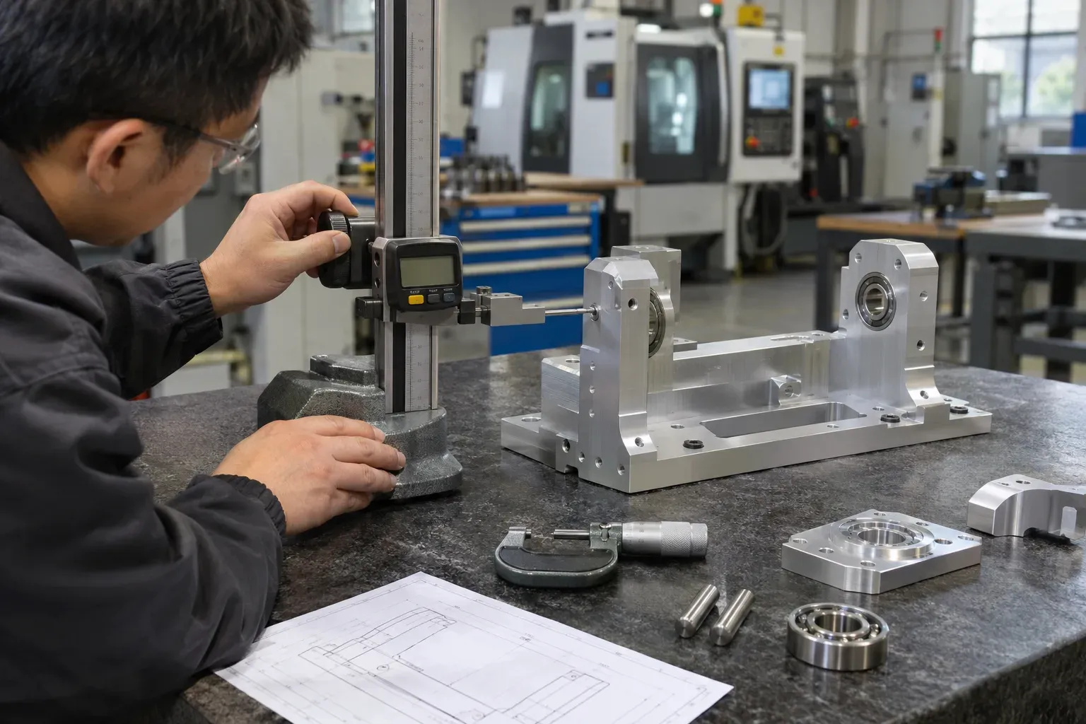
Consider a familiar failure pattern: every component has passed inspection. The bores are within tolerance, the plates are flat, and the shafts match the drawing. Yet during assembly, some bearings seat correctly while others develop drag. No single dimension is out of specification; the accumulated variation is the problem.
That is tolerance stack-up: the way individual dimensional and geometric variations accumulate across an assembly. For manufacturers buying custom CNC machined parts, understanding the stack is often the difference between parts that pass inspection and assemblies that work reliably.
This guide explains how buyers, design engineers, quality teams, and machining suppliers can control tolerance stack-up before it becomes an assembly delay, a sorting operation, or a field failure.
The Short Answer
Do not assign tight tolerances to every dimension and assume the assembly will work. First identify the functional requirement: clearance, preload, alignment, position, sealing, or motion. Build the dimensional chain between the features that control that function. Include geometric tolerances, coating thickness, temperature, and assembly conditions. Then allocate the available variation to the dimensions that the process can control and inspect consistently.
For critical assemblies, review the stack before releasing the RFQ, verify it with first-article parts, and define how production measurements will be linked to the functional result.
What Tolerance Stack-Up Actually Means
A tolerance stack is a chain of dimensions that connects two functional features. The chain may be simple, such as the clearance between a shaft and a bore, or it may cross several machined parts, locating pins, spacers, bearings, coatings, and mounting faces.
Imagine an assembly in which a motor shaft must align with a bearing mounted in a separate housing. The final alignment is influenced by the shaft diameter, bearing internal geometry, housing bore, bore position, housing mounting face, base-plate hole pattern, dowel locations, and the flatness of the mating surfaces. Each feature can be acceptable by itself while the final axis alignment is unacceptable.
The drawing controls individual features. The stack controls the assembly result.
Why Parts Can Pass Inspection but Fail in Assembly
Inspection reports often show each dimension independently. Assembly performance depends on how those dimensions interact.
Common reasons for the gap include:
- The drawing dimensions the part from convenient edges instead of functional datums.
- Linear tolerances are checked, but position, perpendicularity, flatness, or runout is not included in the stack.
- Mating parts were designed or sourced separately without a shared datum strategy.
- Surface treatment thickness changes a bore, shaft, slot, or locating face.
- Flexible parts are measured in one condition and assembled in another.
- A prototype was hand-fitted, hiding a production stack problem.
- Inspection data confirms conformance but does not simulate the worst functional combination.
When an assembly problem appears, tightening every tolerance is an expensive reaction. The better response is to identify which features actually drive the failure.
Start with the Functional Requirement
Before calculating a stack, state what the assembly must achieve.
Typical requirements include:
- Minimum running clearance
- Maximum allowable play
- Bearing preload
- Gear or pulley alignment
- Seal compression
- Connector engagement
- Hole-to-hole assembly clearance
- Tool-center position
- Parallel motion between guides
- A controlled air gap or optical distance
Write the requirement as a measurable output. “The assembly must fit” is not enough. A more useful statement is: “The shaft must rotate without binding while radial play remains below the functional limit across the operating temperature range.”
Once the output is clear, the team can identify every contributor between the two functional endpoints.
Build the Dimensional Chain
Trace the shortest physical path through the assembly from one functional feature to the other. Include only dimensions that change the result, but do not ignore geometric controls.
For an axial bearing stack, contributors might include a shoulder location, bearing width, spacer thickness, housing depth, cover thickness, gasket compression, and coating buildup. For a linear guide assembly, the chain may include the rail locating face, base flatness, dowel position, carriage height, fixture plate thickness, and the perpendicularity of an end bracket.
Use signed dimensions so the calculation reflects direction. Dimensions that increase the gap are positive; dimensions that reduce it are negative. This prevents a long list of tolerances from becoming a calculation that looks precise but does not represent the assembly.
Worst-Case and Statistical Analysis
Two common methods are used to evaluate the stack.
Worst-case stack-up
Worst-case analysis adds the maximum possible contribution from every tolerance in the direction that produces the most unfavorable result. It answers: will the assembly still function if every feature reaches its allowed limit at the same time?
This method is appropriate when failure is unacceptable, production volume is low, the process distribution is not known, parts from different batches or suppliers may be mixed, or selective assembly is not permitted.
The tradeoff is cost. A strict worst-case requirement can force tighter component tolerances than the function or process really needs.
Statistical stack-up
Statistical methods recognize that independent process variations are unlikely to reach all limits in the same direction simultaneously. They can support wider component tolerances while maintaining a high probability of successful assembly.
However, statistical analysis needs real process information. It should not be used merely to make an impossible stack look acceptable. The process must be stable, centered, measured, and monitored. Correlated dimensions, tool wear, common datums, temperature, and batch-to-batch shifts must also be considered.
For a new supplier or a new process, use conservative assumptions until production data supports a statistical model.
Linear Tolerances Are Only Part of the Stack
Many assembly failures come from geometric variation rather than size alone.
A bearing bore can have the correct diameter but be out of position. Two mounting faces can have the correct distance but not be parallel. A shaft can meet its diameter tolerance while runout causes rotation problems. A locating pin can be the right size while its position shifts the entire assembly.
Depending on the function, the stack may need to include:
- True position
- Flatness
- Parallelism
- Perpendicularity
- Profile
- Runout
- Concentricity or coaxiality requirements expressed through suitable controls
- Datum shift at maximum material condition
The datum reference frame should reproduce how the part is located in the assembly. If inspection locates the part differently from the product, the report may not predict assembly behavior.
Hole Patterns, Fasteners, and Locating Pins
Bolts and dowel pins serve different purposes. Bolts usually clamp; dowels usually locate. Treating bolt clearance holes as precise location features can create unpredictable alignment, while using too many rigid locating pins can overconstrain the assembly.
For mating hole patterns, evaluate both the fastener clearance and the positional tolerance of the holes. If dowels establish location, define which part carries the press fit, which part has the slip fit, and how the datum scheme relates to the dowels.
Ask whether the assembly needs repeatable disassembly. A fit that works once under a press may not support maintenance, field replacement, or interchangeable spare parts.
Fits, Bearings, and Rotating Components
Shaft and bore fits are among the most sensitive stacks in machined assemblies. The correct fit depends on load direction, which ring rotates, temperature, material, wall thickness, surface finish, and the assembly method.
A nominal diameter and a general tolerance are rarely enough for a critical bearing seat. Consider roundness, cylindricity, shoulder squareness, surface roughness, and the relationship between multiple bearing bores. A thin housing may also distort after clamping or after a press fit is installed.
When two bearings share an axis, control the features from a functional datum or machine them in a process that preserves their relationship. Measuring each bore separately does not automatically prove coaxial performance.
Finishing and Post-Processing Can Change the Stack
Anodizing, plating, paint, heat treatment, and finish grinding can change dimensions or functional surfaces. Conversion coatings and passivation are usually much thinner, but should still be reviewed where surface condition or a very small clearance matters.
The drawing should state whether dimensions apply before or after finishing. Identify masked bores, threads, locating faces, electrical contacts, and bearing seats. Where coating contributes to both sides of a feature, account for the dimensional effect correctly.
Do not assume a supplier will know which surfaces are allowed to build up. A small coating change on several mating features can consume the entire assembly clearance.
Temperature and Material Matter
Assemblies are often inspected near room temperature and operated somewhere else. Aluminum, steel, stainless steel, engineering plastics, and composites do not expand at the same rate. A clearance that is comfortable during inspection may shrink during operation, while a preload may disappear.
Long dimensions magnify thermal effects. Plastic parts may also absorb moisture or creep under load. Thin metal components can move after stress relief, heat treatment, or material removal.
For temperature-sensitive assemblies, define the operating range and the reference temperature for inspection. Evaluate the stack at the conditions that matter, not only at the metrology-room condition.
A Practical Example: Bearing Housing on a Base Plate
Consider a bearing housing mounted to a machined base plate and aligned by two dowel pins. A shaft must pass through the bearing and engage a motor coupling.
The functional result is shaft-to-motor alignment. Contributors may include the motor pilot fit, motor mounting-hole clearance, coupling flexibility, base-plate flatness, dowel positions, housing mounting-face perpendicularity, bearing-bore position, bearing fit, and shaft runout.
If the housing bore is inspected only from its outside edges, while the assembly is located by dowels and a mounting face, the inspection coordinate system does not match the assembly. Reframing the drawing around the functional datums can make the same manufacturing capability produce a more predictable result.
The solution may be to tighten one critical positional control, loosen several nonfunctional dimensions, define the dowel fit, mask the bearing bore during finishing, and inspect the housing from the same datum surfaces used in assembly. That is usually more effective than tightening every dimension.
How to Allocate Tolerances Without Inflating Cost
Begin with the total variation the function can accept. Reserve margin for contributors that are not controlled by machining, such as purchased-component variation, coating, temperature, assembly force, and wear. Allocate the remaining tolerance to the machined features based on functional sensitivity and process capability.
Features made in the same setup can often be controlled relative to each other more economically than features made across multiple setups. A supplier may recommend changing the datum scheme, machining sequence, locating method, or inspection approach to improve the functional relationship without imposing an unnecessarily tight size tolerance.
Good tolerance allocation is not equal allocation. Give more of the tolerance budget to robust features and less to the contributors that strongly affect the function.
Prototype Verification Before Production
A prototype build should test the stack, not merely prove that one carefully assembled unit can work.
Useful checks include:
- Assemble parts without hand fitting or undocumented rework.
- Measure the functional output as well as the component dimensions.
- Try parts from the high and low ends of key dimensions where practical.
- Record assembly force, clearance, preload, runout, or alignment.
- Confirm finished dimensions after coating and heat treatment.
- Check whether the inspection fixture reproduces the assembly datums.
- Review any shims, sanding, slotting, or selective matching used during the build.
If a technician must choose matching parts or “make it fit,” the process is not yet ready for interchangeable production.
What to Send in the RFQ
For an assembly-sensitive CNC project, send more than isolated part drawings.
Include:
- The latest 2D drawings and 3D models
- An assembly drawing or simplified functional layout
- Mating-part and purchased-component information
- The critical clearance, preload, alignment, or motion requirement
- Functional datums and key GD&T controls
- Material and supplied condition
- Heat treatment, coating, masking, and final inspection condition
- Operating temperature and environment
- Prototype and production quantities
- Required first-article and measurement reports
- Any known assembly failures or previous corrective actions
If the complete assembly is confidential, share a reduced interface model or a marked-up stack diagram that shows only the relationships the supplier needs to review.
Questions to Ask a CNC Machining Supplier
Before placing the order, ask:
- Which dimensions and geometric controls drive assembly function?
- Can the critical relationships be machined in one setup?
- How will the part be fixtured and located during inspection?
- Do the drawing datums match the assembly locating surfaces?
- How will coating, heat treatment, and temperature affect the stack?
- Which features need full inspection, and which can use sampling?
- Can the supplier provide first-article data linked to the functional stack?
- What process changes require notification after approval?
A useful supplier response should discuss the drawing and the assembly mechanism specifically. A generic promise to “hold tight tolerances” does not show that the stack has been understood.
FAQ
Should I use worst-case tolerance stack-up for every assembly?
No. Worst-case analysis is appropriate when every permitted combination must assemble or when process data is limited. Statistical methods may be appropriate for stable, measured production processes, but their assumptions must be justified.
Can GD&T reduce tolerance stack-up problems?
GD&T can control functional relationships more clearly than coordinate tolerances when the datum scheme matches the assembly. It does not remove variation; it defines and communicates the allowable variation more effectively.
Why not tighten every tolerance?
Unnecessary tight tolerances increase machining time, inspection effort, scrap risk, and cost. They may still fail to control the functional relationship if the datum structure or geometric controls are wrong.
Should coating thickness be included in the stack?
Yes, when coating changes a mating size, locating face, thread, seal surface, or clearance. State whether dimensions apply before or after finishing and identify masked features.
What is the best way to validate a stack?
Combine a documented calculation with prototype assembly data and production-capability evidence. Measure the functional output, not only the individual component dimensions.
Final Takeaway
The most expensive tolerance problem is often the one that passes incoming inspection and stops the assembly line. Preventing it requires a shared view of the complete mechanism: functional requirement, datum strategy, dimensional chain, geometric variation, finishing, temperature, process capability, and inspection.
Before requesting a quote, prepare the component drawings, assembly relationship, critical fits, materials, finishing requirements, quantities, and operating conditions. Ask the supplier to review the functional stack and identify the dimensions that need process and inspection controls.