CNC Machining Thread Design Guide: Tapped Holes, Inserts and Inspection
A practical CNC thread design guide covering tapped holes, thread engagement, inserts, blind holes, tolerances, inspection, failure risks, and RFQ requirements.
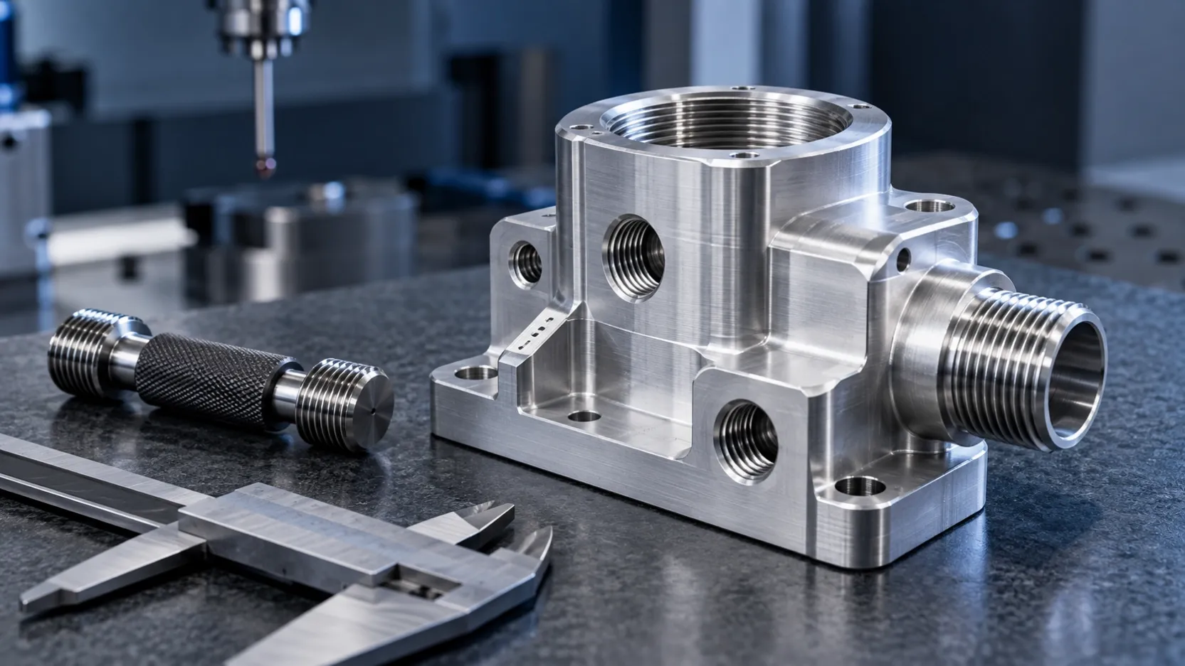
Threads are small features with a large effect on assembly reliability. A thread that looks correct in CAD can still strip, bind, bottom out, leak, or become impossible to inspect if the design does not account for material strength, tool access, thread engagement, hole depth, finish buildup, and production variation. The best thread specification is not the tightest one; it is the simplest specification that gives the joint enough strength, repeatability, and service life.
This guide explains how to design internal and external threads for CNC machined parts, when to use inserts, how blind holes differ from through holes, what inspection can verify, and what information a supplier needs before quoting.
START WITH THE JOINT FUNCTION
Before selecting a thread, define what the fastener must do. Is it clamping two rigid parts, sealing fluid, locating a component, resisting vibration, supporting repeated service, or carrying a structural load? Also identify the expected preload, load direction, operating temperature, corrosion exposure, assembly frequency, and failure consequence.
A lightly loaded enclosure screw has different needs from a hydraulic port, a removable fixture insert, or a threaded shaft carrying cyclic tension. When the function is clear, thread form, size, class, engagement, and inspection can be chosen intentionally.
INTERNAL VS EXTERNAL THREADS
Internal threads are commonly produced by cutting taps, forming taps, thread milling, single-point boring, or specialized tooling. External threads may be single-point turned, die cut, thread milled, rolled, or ground. The preferred method depends on diameter, pitch, material, geometry, quantity, surface requirements, and whether the thread is standard or custom.
Thread milling offers flexibility and good control, especially for larger diameters, difficult materials, interrupted features, or parts where a broken tap would be costly. Tapping is usually efficient for common small holes. Single-point turning is widely used for concentric external threads and larger internal threads on turned parts.
CHOOSE A STANDARD THREAD WHEN POSSIBLE
Standard metric or unified inch threads reduce tooling cost, simplify inspection, and make replacement fasteners easy to source. State the complete designation on the drawing, including nominal size, pitch or threads per inch, internal or external class, and any left-hand requirement.
Avoid specifying a custom diameter or pitch unless the application genuinely requires it. Custom threads may need special tools, gauges, programming, and longer lead times. They also create more opportunity for ambiguity between the drawing, mating component, and inspection plan.
THREAD ENGAGEMENT: MORE IS NOT ALWAYS BETTER
Required engagement depends on the strength of the internal-thread material, fastener strength, thread geometry, load, and safety factor. A common design starting point for many steel joints is approximately one nominal diameter of engagement, while weaker materials such as aluminum or plastics may require more engagement or an insert. This is only a planning rule, not a substitute for an engineering calculation.
Once engagement is long enough for the fastener to reach its intended tensile capacity, additional depth may provide little benefit. Excessive depth increases drilling and tapping time, raises chip-removal risk, and may force the manufacturer to use long, less rigid tools.
BLIND HOLES NEED EXTRA DEPTH
A blind tapped hole cannot provide full usable thread to the drilled bottom. Space is required for the drill point, tap lead, incomplete threads, chip accumulation, and assembly clearance. The drawing should distinguish between drill depth, full-thread depth, and minimum usable engagement.
Calling out a thread “to the bottom” is usually impractical. Instead, specify the minimum full-thread depth needed by the joint and allow the supplier enough additional drill depth. Check that the selected fastener cannot bottom out before clamping the assembly.
THROUGH HOLES ARE USUALLY EASIER
Through tapped holes allow chips and coolant to exit and are generally easier to machine and verify. If function permits, a through hole can reduce broken-tool risk and cycle time. However, consider whether an open hole creates leakage, contamination, cosmetic, or corrosion concerns.
DESIGN FOR TOOL ACCESS
The tool must approach the thread along its axis with enough clearance for the spindle, holder, and gauge. Threads close to shoulders, walls, ribs, or pocket floors may require long-reach tools and special inspection equipment. A thread on an angled face may add a setup or require multi-axis machining.
Provide a chamfer or lead-in at the entrance. It protects the first thread, guides the fastener, and improves assembly. For external threads near a shoulder, provide a practical runout or relief so the cutting tool can complete the profile without crashing into the shoulder.
WHEN TO USE THREADED INSERTS
Helical-wire, key-locking, and solid inserts can strengthen threads in aluminum, magnesium, plastics, and other relatively soft materials. They are also useful when a joint will be assembled many times, when field repair is important, or when a locking feature is needed.
Inserts add component cost and installation steps, so they should be used where they protect function. Define the insert type, material, size, locking feature, installation depth, and applicable standard. Confirm whether inserts are installed before or after coating and whether they must be supplied assembled.
MATERIAL AND PROCESS EFFECTS
Material behavior strongly affects thread production. Aluminum machines efficiently but can gall during assembly and may need an insert for repeated service. Austenitic stainless steels can work harden and may require controlled tooling and lubrication. Hardened steels may need thread milling, grinding, or machining before heat treatment. Plastics can creep under sustained preload and may require coarse threads, inserts, or reduced tightening torque.
Surface treatments also matter. Anodizing, plating, paint, passivation, and thermal treatments can change pitch diameter, friction, or corrosion behavior. State whether the thread requirement applies before or after finishing, whether masking is required, and whether a mating fastener or gauge must pass after coating.
TOLERANCE AND FIT
Standard thread classes already define practical relationships between mating parts. Do not apply unusually tight limits without a functional reason. Tighter fit can increase machining and gauge cost and may become unreliable after finishing or when parts are sourced from different suppliers.
If low backlash, alignment, sealing, or controlled torque is critical, explain the function and define the mating component. A numerical pitch-diameter limit or special gauge may be appropriate, but it should be agreed before production.
THREAD RELIEF, RUNOUT AND CHAMFERS
External threads cut up to a shoulder need room for tool runout. Internal threads close to a bottom have incomplete lead threads. Modeling a theoretically perfect sharp transition does not create a manufacturable feature.
Use recognized relief geometry where appropriate and avoid sharp, fragile thread starts. Chamfers should be large enough to remove burrs and guide assembly without removing excessive first-thread engagement. If the edge is a sealing interface, coordinate the chamfer with the seal design.
COMMON FAILURE MODES
- Internal thread stripping because engagement or material strength is insufficient
- Fastener bottoming in a blind hole before clamp load is achieved
- Galling in stainless-steel or aluminum assemblies
- Cross-threading caused by poor lead-in or misalignment
- Cracked thin walls around an oversized tapped hole
- Binding after anodizing, plating, painting, or heat treatment
- Incomplete threads caused by insufficient tap or tool runout
- Broken taps from deep blind holes, poor chip evacuation, or hard material
- Inspection disagreement because class, gauge, or standard was not stated
INSPECTION OPTIONS
GO/NO-GO plug gauges are commonly used for internal threads, while ring gauges are used for external threads. These functional gauges quickly verify whether the thread accepts the intended limits. Optical systems, thread micrometers, three-wire measurement, coordinate measurement, and pitch-diameter instruments may be used when additional data is required.
A gauge result does not automatically prove every aspect of thread quality. Burrs, damage, surface finish, lead error, coating buildup, and feature position may require separate checks. For critical parts, define the applicable standard, gauge class, inspection frequency, and whether a report is required.
DO NOT FORGET THREAD POSITION
A perfect thread in the wrong location still fails the assembly. Control the axis position and orientation relative to functional datums. If the thread locates a component, consider whether a separate pilot diameter or dowel provides better repeatability than relying on the thread alone.
For threaded features on thin walls or small bosses, check edge distance and remaining material. The boss must support both machining forces and service loads without distortion or breakout.
DRAWING CHECKLIST
- Complete thread designation, pitch, class, and hand
- Quantity and exact feature location
- Minimum full-thread depth or engagement
- Separate drill depth for blind holes when necessary
- Entry chamfer and external-thread runout or relief
- Material and heat-treatment condition
- Insert specification and installation requirement
- Whether acceptance applies before or after surface finishing
- Critical position, orientation, or concentricity controls
- Gauge standard, sampling plan, and reporting requirement
WHAT TO INCLUDE IN AN RFQ
Send the 3D model and controlled 2D drawing together. Include material and temper, quantity, thread specifications, mating-fastener information, heat treatment, surface finish, masking requirements, insert details, expected assembly cycles, and inspection documentation. Highlight any thread that is safety-critical, pressure-containing, difficult to access, or required to pass a mating part after finishing.
If the design is still flexible, tell the supplier which requirements may change. Early review can often replace a deep blind thread, custom pitch, or difficult shoulder runout with a more robust and economical feature.
FINAL GUIDANCE
Reliable CNC threads come from connecting the drawing callout to the real joint. Use standard threads where possible, provide only the engagement the load requires, allow space for tools and incomplete threads, account for finishing, and specify inspection that matches the risk.
Zync Precision can review thread geometry, material, access, inserts, finishing, and inspection before quotation. Send your CAD model, drawing, quantities, and critical assembly requirements through our Request a Quote page for a practical manufacturing review.