CNC Machining Thin Walls: Design, Distortion and Tolerance Guide
A practical guide to thin-wall CNC machining covering minimum wall thickness, deflection, distortion, workholding, material choice, tolerances, inspection, and RFQ requirements.
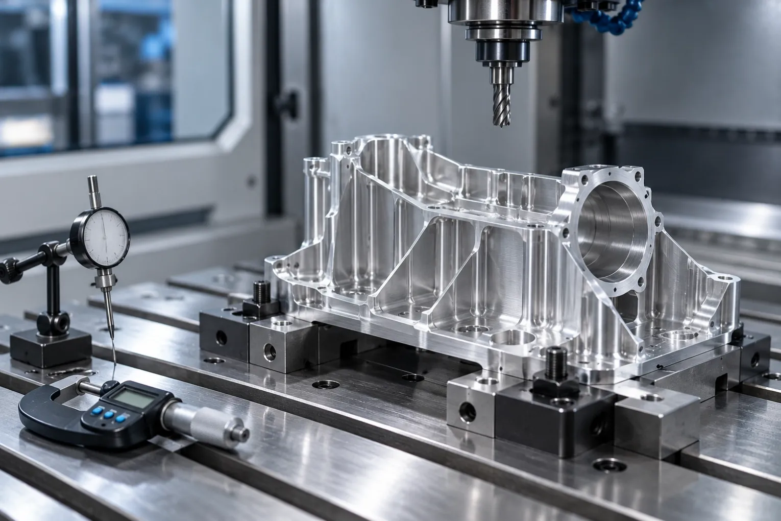
Thin walls help engineers reduce weight, create compact assemblies, and improve thermal performance. They also remove the stiffness that makes a part easy to machine. Under cutting force, clamping pressure, heat, and residual stress, a thin feature can deflect during machining and move again after the fixture is released.
The result may be a wall that measures correctly in the machine but falls out of tolerance at final inspection. This guide explains how to design thin-wall CNC parts for predictable quality, how manufacturers control distortion, and what buyers should include in an RFQ.
What Counts as a Thin Wall in CNC Machining?
There is no universal thickness at which a wall becomes “thin.” Machinability depends on the ratio between wall height, thickness, unsupported length, material stiffness, geometry, and tolerance.
A 1.0 mm aluminum wall that is 8 mm high and supported on three sides may be straightforward. The same thickness at 60 mm high, open on both ends, and controlled to a tight profile tolerance is a very different problem. For this reason, minimum-wall-thickness charts should be treated as early design guidance rather than guaranteed capability.
As a general starting point, many CNC designs use walls of about 0.8–1.0 mm in aluminum, 1.0–1.5 mm in steel, and 1.5–2.0 mm in engineering plastics. Smaller walls are possible, but the process may require specialized tooling, staged material removal, custom support, additional inspection, or a different manufacturing method.
Why Thin Walls Move
Cutting-force deflection
An end mill pushes against the workpiece. A rigid section resists that load; a thin wall bends away from the cutter. When the tool passes, the wall springs back, leaving taper, waviness, or excess material. Increasing wall height or unsupported length makes this effect much stronger.
Clamping distortion
Vise jaws, clamps, and expanding mandrels can deform a flexible part. If a feature is finished while the part is distorted, it may change size after unclamping. More clamping force is not always safer; support location and load distribution matter more.
Heat
Machining creates heat in the tool, chips, and workpiece. Thin sections have little thermal mass and can change temperature quickly. Uneven heating may cause temporary dimensional growth or local warping, especially during long finishing passes.
Residual stress
Rolled plate, extrusions, forgings, castings, and heat-treated stock contain internal stress. Removing material changes the balance of that stress. A part may bow during roughing, after release from the fixture, during finishing, or even after a secondary process.
Stress from secondary operations
Anodizing, plating, heat treatment, welding, blasting, and aggressive polishing can affect a thin component after machining. The drawing should define whether final dimensional requirements apply before or after finishing.
Design Guidelines for More Stable Thin Walls
Keep thickness uniform where possible
Abrupt transitions between thick and thin sections concentrate stiffness changes and can increase distortion. A more uniform wall generally responds more predictably to cutting and temperature. If a transition is necessary, use a gradual blend or fillet rather than a sharp step.
Reduce unsupported height and length
Add ribs, gussets, flanges, return edges, or temporary bridges when the function permits. A small increase in structural support can be more effective than a large increase in wall thickness. Support on two or three edges is much more stable than a tall cantilevered wall.
Use generous internal corner radii
Deep pockets with small internal radii require long, slender tools. These tools deflect more, vibrate more easily, and remove material less efficiently. Larger radii allow a stiffer cutter and smoother toolpath. A useful early rule is to make the internal radius at least one-third of the pocket depth where geometry allows; deeper pockets may need more.
Avoid unnecessarily deep narrow pockets
Pocket depth, corner radius, and wall thickness must be considered together. Deep cavities limit tool access and chip evacuation while increasing the wall’s unsupported height. Dividing one deep pocket into stepped levels can improve rigidity and reduce risk.
Add a functional tolerance, not a blanket tolerance
A tight general tolerance on every wall can add machining passes, inspection time, and scrap risk without improving the assembly. Identify the surfaces that locate, seal, guide, or interface with other parts, then apply tight controls only where they support function.
Define the free-state condition
Flexible parts can measure differently when clamped, held by hand, or resting naturally. If inspection must be performed in a constrained condition, define the fixture, support points, and clamping load. Otherwise, specify that requirements apply in the free state.
Material Choice and Thin-Wall Behavior
Aluminum alloys
Aluminum is common for thin-wall housings because it is lightweight and generally machines well. 6061-T6 offers a useful balance of machinability, corrosion resistance, and dimensional predictability. 7075-T6 provides higher strength but may cost more and requires appropriate corrosion protection for some environments. Stock form and heat-treatment history can be as important as alloy name.
Stainless steel
Stainless steel is stiffer than aluminum but produces higher cutting forces and may work-harden. Heat control, sharp tools, and stable engagement are important. Thin stainless features may spring or vibrate even when their nominal thickness appears conservative.
Engineering plastics
Plastics have lower stiffness and can be sensitive to heat, moisture, and internal stress. They often need very sharp tools, low clamping pressure, controlled temperature, and time to stabilize before final measurement. A wall thickness that is comfortable in aluminum may be unreliable in POM, nylon, PTFE, or PEEK.
How Machinists Control Thin-Wall Distortion
Balance material removal
Removing most of the stock from one side first can unbalance residual stress. A common strategy is to rough opposing sides in stages, turn or re-fixture the part, and leave consistent stock for finishing.
Leave support until late in the process
Tabs, sacrificial ribs, an uncut floor, or temporary bridges can support a wall during roughing. The support is removed only after critical features are nearly complete. This may add operations, but it often improves repeatability.
Use light, consistent finishing passes
Heavy finishing cuts can push the wall away. Light radial engagement, sharp tools, controlled feed, and consistent toolpaths reduce the change in cutting load. Climb milling is commonly used where the machine, fixture, and geometry make it appropriate.
Apply toolpaths designed for constant engagement
Adaptive or high-efficiency roughing strategies reduce sudden load changes. Trochoidal motion and gradual entries can be helpful in deep cavities. The objective is not simply to cut slowly; it is to maintain a stable, predictable force.
Support the wall close to the cutting zone
Custom soft jaws, vacuum fixtures, low-melting support media, machinable fillers, and conformal fixtures may be used for difficult parts. The support method must avoid marking the component, trapping contamination, or introducing a new distortion.
Control clamping force
Torque-controlled fasteners, distributed clamps, large contact areas, and machined soft jaws help prevent local deformation. The fixture should locate the part repeatably without using the flexible wall as the primary datum whenever possible.
Allow relaxation between operations
For sensitive parts, the manufacturer may rough the component, release it, allow it to stabilize, and then re-machine the datums before finishing. A stress-relief treatment may be considered for suitable metals, but its effect on material condition and final properties must be reviewed.
Tolerances and GD&T for Thin-Wall Parts
Size tolerances alone rarely describe a flexible housing completely. Profile of a surface can control a complex wall relative to a datum reference frame. Flatness may be appropriate for a free surface, while perpendicularity or parallelism can relate it to a functional interface.
Datum selection is critical. Use stable, accessible surfaces that represent how the part functions in the assembly. Avoid choosing a narrow flexible edge as the primary datum unless that is truly how the part is located.
For walls that mate with a cover, gasket, bearing, or PCB, separate the critical interface from cosmetic surrounding geometry. State whether the inspection is performed before or after coating, and identify any areas that may be masked.
Inspection Challenges
Contact measurement can move the feature being measured. A CMM probe with excessive force, a micrometer squeezed too tightly, or a fixture that overconstrains the part may create a false result.
Appropriate inspection may include:
- low-force CMM probing;
- optical measurement or structured-light scanning;
- air gauges for suitable bores;
- dedicated checking fixtures;
- multiple measurements after part relaxation;
- temperature-controlled inspection; and
- wall-thickness mapping rather than a single point.
The inspection method should match the tolerance and the feature’s flexibility. For production parts, agree on sampling frequency and the reporting format before manufacturing begins.
Common Thin-Wall Failure Modes
Tapered walls: the cutter deflects differently from top to bottom.
Chatter marks: the wall or tool vibrates, causing a repeated surface pattern and inconsistent size.
Bowing after unclamping: clamping force or residual stress was released after finishing.
Out-of-flat sealing faces: uneven material removal or thermal effects changed the interface.
Cracks at sharp transitions: local stress concentration was increased by geometry, machining stress, or service load.
Coating-related fit problems: thickness buildup or post-process distortion was not included in the tolerance plan.
RFQ Checklist for Thin-Wall CNC Parts
Send enough information for the supplier to evaluate risk rather than quoting only from a simplified model.
- Native 3D CAD and a controlled PDF drawing
- Material alloy, condition, and preferred stock form
- Critical wall thicknesses and maximum unsupported heights
- Functional datums and GD&T requirements
- Free-state or constrained-state inspection condition
- Surface-finish requirements only where functional
- Heat treatment, anodizing, plating, passivation, or coating details
- Quantity, prototype quantity, and expected repeat demand
- Cosmetic zones and acceptable fixture witness areas
- Inspection report, material certificate, or traceability requirements
- Mating-part information for critical interfaces
- Packaging requirements for fragile walls and edges
If a wall is unusually thin, ask the supplier to review the geometry before the purchase order. A small design change—such as adding a rib, increasing a corner radius, or relaxing a nonfunctional tolerance—can improve yield and reduce cost far more than negotiating cycle time later.
Final Design Guidance
Successful thin-wall CNC machining is a system problem. Wall thickness, unsupported height, material condition, tool access, fixture strategy, machining sequence, finishing, and inspection all interact. The most reliable drawings describe function clearly and give the manufacturer room to choose a stable process.
Zync Precision supports prototype and low-volume CNC machined parts in aluminum, stainless steel, engineering plastics, and other materials. Share your 3D model, drawing, quantity, finish, and inspection requirements for a manufacturability review and quotation.