CNC Machining Guides
CNC Hydraulic Manifolds: Design, Tolerances & RFQ Guide
A buyer's guide to CNC machined hydraulic manifolds: port and cavity standards, cross-drilled holes, wall thickness, sealing faces, deburring, inspection, pressure testing, and RFQ inputs.
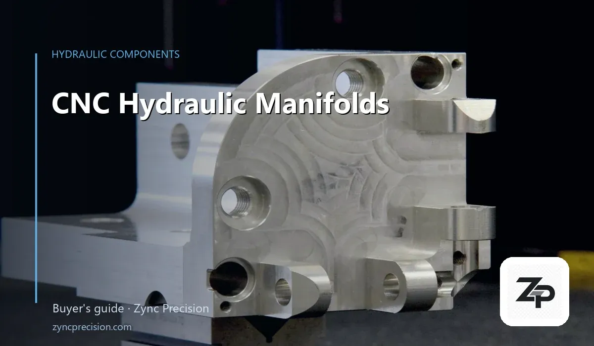
A hydraulic manifold looks like a block with holes. The quote depends on where those holes intersect, how the ports are threaded, how deep the cavities are, how clean the internal passages must be, and who pressure-tests the finished block.
A manifold is a compact way to route fluid between a pump, valves, actuators, and sensors. Every drilling, port, cavity, and sealing face affects flow, pressure, leak risk, and serviceability.
This guide is for hydraulic equipment OEMs, valve distributors, system integrators, and MRO buyers who need a machined manifold that fits the circuit and the test requirement, not just a block with the right outside dimensions.
The Short Answer
CNC machining is usually the right choice for custom manifolds at low-to-medium volume, for aluminum or steel blocks, for complex internal circuits, and when the design may change. It avoids tooling and can hold tight port positions and sealing faces.
A cast or forged block plus machining can be economical at higher volume when the external shape is stable and the internal circuit is simple. A standard manifold block may be cheaper than a custom one if the circuit fits a catalog pattern.
The decision is not only machining versus casting. It is how the block is made, how the circuit is drilled, how the ports are sealed, and how the finished manifold is tested.
What a Hydraulic Manifold Actually Does
The block connects ports and passages. Cartridge valves, directional valves, pressure controls, flow controls, accumulators, and sensors mount on the block. Internal drillings connect the ports; cross-drillings create junctions; plugs close the ends of drillings that are not used as ports.
The outside shape is only the envelope. The value is in the internal circuit: passage size, intersection geometry, port position, cavity depth, and the cleanliness of the passages.
A manifold that looks correct on the outside can fail because a cross-hole leaves a burr, a thread breaks into a passage, a cavity is too shallow, or a sealing face is not flat.
Material Choice
Aluminum 6061 is common for lower-pressure hydraulic and pneumatic manifolds because it is easy to machine and light. 7075 offers higher strength but can be less corrosion-resistant without a finish. Steel and stainless steel are used for higher pressure, aggressive environments, or specific customer standards. Ductile iron is common for cast manifolds.
The material affects more than strength. It affects thread strength, corrosion, weight, thermal expansion, and the finishing options. Specify the grade and condition, and ask for a material certificate if the manifold is safety-related or traceable.
Do not choose a material only because it is easy to machine. Check the operating pressure, fluid, temperature, and environment with the hydraulic engineer.
Ports and Cavities: The Standards Matter
Port threads and cavities are not generic. SAE J1926/ISO 11926, BSPP ISO 1179, NPT, and metric ports have different thread forms, spotface diameters, and sealing methods. A drawing that says '1/2 port' without a standard is ambiguous.
Cartridge valve cavities also follow standard or supplier-specific patterns. The cavity diameter, depth, angles, and thread must match the valve. A few tenths of a millimeter can change the seal and the valve position.
State the standard, the size, the thread class, the spotface, and the depth. If a cavity insert or form tool is required, say who supplies it and whether it is available.
Cross-Drilled Holes and Wall Thickness
Cross-drilled holes are the heart of a manifold and the main source of scrap. The drill can wander, break into another passage at an awkward angle, leave a burr, or create a thin wall between passages.
Design the circuit with enough wall thickness between passages and to the outside. Avoid placing threads at a cross-hole intersection. Use spotfaces for port seals, and leave clearance for the drill point at the end of a blind passage.
If a passage must intersect another at a sharp angle, expect a burr and a more difficult deburring operation. A small change in the drill position or angle can remove the problem before the first chip is cut.
Sealing Faces and Surface Finish
O-ring ports, gasket faces, and valve mounting surfaces need flatness, surface finish, and scratch-free sealing. A Ra callout alone does not describe a scratch, a step, or a burr across the seal path.
Specify the sealing method, the surface finish, the flatness, and the inspection. If the face will be anodized or painted, say whether the finish applies to the sealing surface; masking may be required.
For O-ring grooves, specify the groove dimensions, the surface finish, and the corner radius. A sharp edge can cut the O-ring during assembly.
Deburring and Cleanliness
Every drilled passage can leave a burr at the intersection. A burr can break loose, travel through the circuit, and damage a valve or a seal. Deburring is not cosmetic; it is a functional requirement.
Specify the deburring method or the acceptance criteria. Brush deburring, abrasive flow, thermal deburring, and manual work are options, but each has limits. If cleanliness matters, specify an ISO 4406 code or your internal particle limit, and say how it will be verified.
A manifold can pass a dimensional inspection and still fail because it is not clean. Put the cleanliness requirement on the drawing and in the purchase order.
Machining Process and Setups
A manifold usually needs multiple setups: face and bore one side, then the next, then the ports, then the cavities. Each setup adds alignment and tolerance stack-up. A well-designed block puts related features on the same face and uses a consistent datum.
Five-axis machining can reduce setups for angled ports and complex faces, but it is not always necessary. A three-axis machine with good fixtures can be efficient for a simple block. The process should match the geometry, not the catalog.
Thread milling or tapping, boring, reaming, and cavity tools all have their own time and tooling. A manifold with many small ports and deep cavities takes longer than the outside dimensions suggest.
Tolerances and Inspection
Critical dimensions usually include port position, thread size and depth, cavity dimensions, sealing-face flatness, surface finish, and passage cleanliness. The drawing should say which features are critical and how they will be measured.
Inspection can include a first article, CMM checks, thread gauges, cavity gauges, surface finish measurement, and a pressure or leak test. If a pressure test is required, agree on the test pressure, duration, fluid, temperature, acceptance criteria, and who performs it.
Do not assume the machinist will pressure-test the manifold. A machining supplier may not have the test bench or the hydraulic expertise. Define the test scope before the quote, not after the parts are made.
Cost Drivers Buyers Should Compare
The cost of a manifold is driven by block size and material, the number of ports and cavities, the number of setups, special tools, deburring and cleaning, inspection, and pressure testing.
A larger block does not always cost more than a small complex block. A small block with 20 cross-drilled passages and 10 cavities can take longer than a large block with a simple circuit.
Ask for the cost breakdown: material, programming, setup, machining, deburring, cleaning, inspection, test, and finishing. Compare the same scope, especially the test and documentation.
Design Rules for Manifolds
Keep passages short and direct. Avoid unnecessary bends and dead ends. Use the largest passage that the flow requires, but check the wall thickness. Place ports where the wrench and hose have access.
Group features by face to reduce setups. Use standard port and cavity sizes. Avoid threads that break into a cross-passage. Leave room for plugs and service access. Design the mounting pattern so the block can be held securely during machining.
If the block will be anodized, note that anodizing can change dimensions and sealing surfaces. Mask threads and sealing faces, or specify the finish before anodizing.
RFQ Checklist
Send the 3D model in STEP format, the 2D drawing with port and cavity standards, the material and condition, the operating pressure and proof/test pressure, the fluid and flow, the surface finish, the cleanliness requirement, the test standard, the quantity, and the target date.
Mark the critical dimensions and the sealing faces. State who supplies the cartridge valves, and whether the cavity tools are standard or supplier-specific. Tell us if the block is a prototype or a repeat production part.
If the circuit is still being developed, say which passages may change. A machined prototype can validate the circuit before a casting or a production tool is committed.
Common Mistakes
Using a port callout without a standard, such as '1/2 inch' instead of SAE, BSPP, NPT, or metric.
Putting a thread at a cross-hole intersection, or leaving too little wall between passages.
Forgetting the spotface or the drill point clearance.
Specifying a cosmetic finish on a sealing face without masking.
Assuming pressure testing is included when it is not.
Not specifying deburring or cleanliness, then finding a burr during assembly.
Choosing a cavity without confirming the valve supplier and the tool availability.
Prototype, Bridge, and Production
A machined manifold is a practical way to validate a circuit before committing to a casting or a dedicated production process. The same block can be revised quickly if a passage or port changes.
At higher volume, a cast or forged block with machining may reduce material and cycle time. The design must include machining allowance, draft, and stable datums. The machinist and the foundry should agree on the interface.
Zync Precision machines hydraulic manifolds and valve bodies from solid blocks and from castings or forgings. We do not supply the cartridge valves, but we can machine the cavities and ports to the valve supplier's drawing.
How to Get a Useful Quote
Send the drawing, material, operating pressure, port and cavity standards, test requirement, quantity, and target date to emily@zyncprecision.com. Tell us whether the block is a prototype, a bridge batch, or a production part.
We will review the circuit for wall thickness, tool access, setups, deburring, and inspection, and reply with a practical quote within 24 hours. If a design change would reduce cost or risk without changing the circuit, we will tell you before machining.
FAQ
Can you machine a manifold from a casting?
Yes. We review the casting allowance, datums, and critical faces, and machine the ports, cavities, and sealing surfaces. Porosity can appear during machining, so the acceptance criteria should be agreed before production.
Do you pressure-test manifolds?
Tell us the test standard and acceptance criteria. We will confirm whether the test is performed in-house or by a qualified test partner, and include it in the quote. Do not assume it is included by default.
What material should I use?
It depends on pressure, fluid, temperature, corrosion, weight, and the customer standard. Aluminum 6061 is common for lower-pressure manifolds; steel, stainless, and ductile iron are used where the application requires them.
Can you match a competitor's manifold?
Yes, if you provide the drawing, the valve/cavity standard, and the interface dimensions. We will review the critical features and tell you if the drawing is complete enough to machine.
A Practical Next Step
Send your manifold drawing and operating pressure to emily@zyncprecision.com. We will review the ports, cavities, wall thickness, deburring, and test requirement, and reply with a quote within 24 hours. If the circuit is still changing, a machined prototype is the fastest way to validate it.